JEXtream® Wi-Fi 6 AX1800 Router
Quick Start Guide & Installation
1. Package Contents
Before beginning terminal setup, verify that all hardware components are present in your deployment kit:
| Core Terminal Unit | JEXtream FX20 Router |
| Power Interface | Dedicated Power Adapter |
| Wired Data Link | LAN Connection Cable |
| Documentation Kit | Quick Start Guide Document |
2. Hardware Provisioning & Configuration
Follow the cabling diagram below to establish correct power alignment and wide-area network routing links:
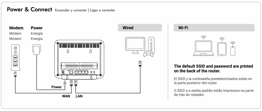
- Physical Power & Connection: Interconnect your host internet modem to the router's physical WAN port via data cabling, attach the dedicated power adapter to the hardware power interface, and connect your client devices using physical LAN wiring or over Wi-Fi channels.
- Localized Web UI Administration: Establish a data link to the router terminal, open a secure web browser window, and navigate directly to
router.jextream.netor routing IP address192.168.10.1. - Default Access Credentials: Input the factory administrative login management password printed explicitly on the product label situated on the back plane of the router terminal.
- Wireless Client Authentication: Connect wireless hardware using the factory-assigned broadcast SSID profile string and secure security passcode key found printed on the back panel of the unit.
- Mobile Application Alternative: Download and deploy the corporate SEIONA management framework app accessible over the iOS App Store platform or Google Play Store services to provision settings.
3. Diagnostic Troubleshooting
Execute the following systematic mitigation steps if your local network architecture encounters broad WAN internet link errors:
| Step 1: Cycle Power | Power down the internal router circuitry completely and safely disconnect the physical WAN communication link cable. |
| Step 2: Reseat Cabling | Firmly re-engage the physical WAN connection cable directly back into the router interface array port. |
| Step 3: Device Reboot | Initiate a cold system reboot sequence on the primary router node. |
| Step 4: Status LEDs | Monitor structural indicator lights on the forward panel assembly during the initialization lifecycle: • Power LED: A solid amber illumination element indicates active core operational state parameters. • WAN LED: Wait 30 to 60 seconds. Solid or flashing amber signals valid internet sync. An inactive, dark indicator confirms a complete data timeout (verify link cords or consult your Internet Service Provider). |
4. Operational Safety Precautions
Adhering strictly to standard engineering safety protocols avoids physical component damage and preserves user warranty coverage protections:
- Environmental Placement: Maintain clear physical distance from local vibrating structures, stray magnetic interference patterns, direct exposure to solar tracking rays, or open thermal combustion zones.
- Wired Power & Extension: Deploy the terminal exclusively using the official factory power transformer interface module. Avoid overextending structural electrical capacities if linking to secondary multi-outlet extension bars.
- Enclosure Protection: Exercise intense care with unsealed liquid containers situated around system housings, do not block open ventilation tracks, and refrain from performing manual casing alterations or hardware repairs.
- Technical Resource Retrieval: If basic data link errors persist across the terminal environment, visit the global corporate node at
www.seiona.comor retrieve complete user manual documents.
Was this article helpful?
That’s Great!
Thank you for your feedback
Sorry! We couldn't be helpful
Thank you for your feedback
Feedback sent
We appreciate your effort and will try to fix the article